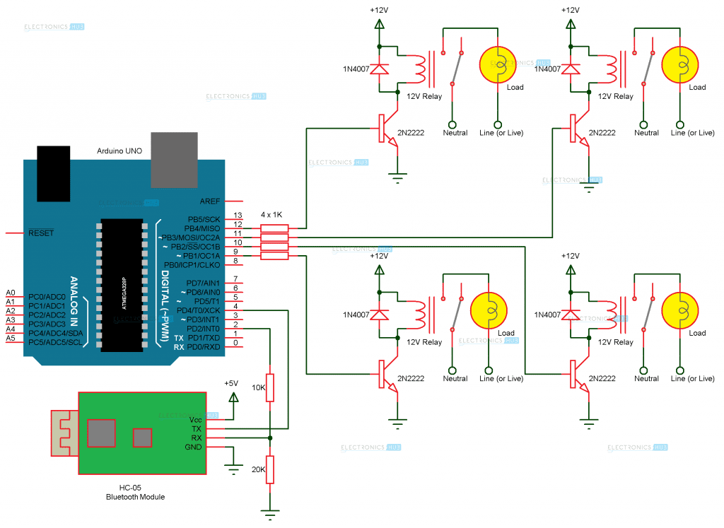
Circuit Diagram
ส่วนHardware (input,Output)
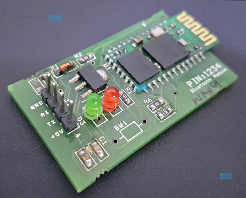
1.Bluetooth Module:
The Bluetooth Module used in this project is HC- 05. As seen in the image below, this Bluetooth module has 4 – pins for VCC (5V), ground, TX and RX.
This Bluetooth can be used with Bluetooth enabled phone (or tablet or laptop) and the range of this module is approximately 10 meters.
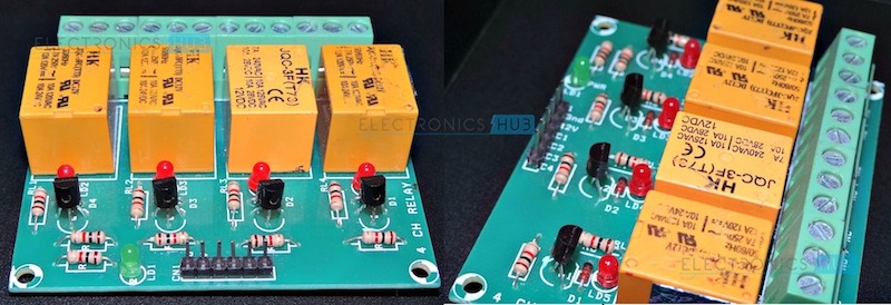
2. 4-Channel Relay Board:
A 4 – channel relay board is used in this project to control four different loads. It has all the necessary components and connections like base current limiting resistor, flyback diode, LED indicators and header for connecting it to other devices.
Caution: We should be very careful when using a relay with AC mains.
Code
| ส่วนหัวโปรแกรม
#include <SoftwareSerial.h> //ฟังชั่นพิเศษ กำหนม library ที่เราเรียกใช้งาน |
| |
| const int rxPin = 4; //กำหนดตัวแปร rxPin = ขา 4 |
| const int txPin = 2; //กำหนดตัวแปร rxPin = ขา 2
|
| |
| SoftwareSerial mySerial(rxPin, txPin); |
| |
| const int Loads[] = {9, 10, 11, 12}; |
| |
| int state = 0; |
| int flag = 0; |
| ส่วนตัวโปรแกรมมี 2 ส่วน |
| 1.void setup() //เป็นฟังชั่นแรกเมื่อ Arduino ทำงาน |
| { |
| for (int i=0;i<4;i++) //สั่งให้ทำซ้ำไปเรื่อยๆ |
| { |
| pinMode(Loads[i], OUTPUT); //กำหนดให้ Loads เป้น OUTPUT |
| } |
| mySerial.begin(9600); //กำหนมความเร็วในการส่งข้อมูล |
| for (int i=0;i<4;i++) //ทำซ้ำไปเรื่อยจนครบตามเงื่อนไข |
| { |
| digitalWrite(Loads[i], LOW); สั่งให้ loads เป็น LOW |
| } |
| |
| } |
| |
| 2.void loop() //การทำงานซ้ำไปเรื่อยๆ |
| { |
| |
| if(mySerial.available() > 0) เช็คขอมูลในเงื่อนไขว่าเป็นจริงหรือไม่ |
| { |
| state = mySerial.read(); อ่านค่าที่ได้รับ |
| flag=0; |
| } |
| |
| switch(state) |
| { |
| case '0':digitalWrite(Loads[0], HIGH); เมื่อกดสวิต 1 ให้ loads เป็น 1 |
| flag=1; |
| break; |
| case '1':digitalWrite(Loads[0], LOW); เมื่อกดสวิต 2 ให้ loads เป็น 0 |
| flag=1; |
| break; |
| case '2':digitalWrite(Loads[1], HIGH); |
| flag=1; |
| break; |
| case '3':digitalWrite(Loads[1], LOW); |
| flag=1; |
| break; |
| case '4':digitalWrite(Loads[2], HIGH); |
| flag=1; |
| break; |
| case '5':digitalWrite(Loads[2], LOW); |
| flag=1; |
| break; |
| case '6':digitalWrite(Loads[3], HIGH); |
| flag=1; |
| break; |
| case '7':digitalWrite(Loads[3], LOW); |
| flag=1; |
| break; |
| case '8':digitalWrite(Loads[0], LOW); |
| digitalWrite(Loads[1], LOW); กำหนดให้สั่งเป็น LOW ทั้งหมด |
| digitalWrite(Loads[2], LOW); |
| digitalWrite(Loads[3], LOW); |
| flag=1; |
| break; |
| } |
| }
จบการทำงานของโปรแกรม.. |
Flowchart
 This Bluetooth can be used with Bluetooth enabled phone (or tablet or laptop) and the range of this module is approximately 10 meters.
2. 4-Channel Relay Board:
A 4 – channel relay board is used in this project to control four different loads. It has all the necessary components and connections like base current limiting resistor, flyback diode, LED indicators and header for connecting it to other devices.
This Bluetooth can be used with Bluetooth enabled phone (or tablet or laptop) and the range of this module is approximately 10 meters.
2. 4-Channel Relay Board:
A 4 – channel relay board is used in this project to control four different loads. It has all the necessary components and connections like base current limiting resistor, flyback diode, LED indicators and header for connecting it to other devices.
 Caution: We should be very careful when using a relay with AC mains.

ไม่มีความคิดเห็น:
แสดงความคิดเห็น